
So my goal in this project is to create a network of temperature and humidity sensors, using the ESP8266’s. To facilitate this I purchases a pack of these sensors:
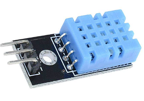
These were the specific ones I bought:
https://www.amazon.com/HiLetgo-Temperature-Humidity-Arduino-Raspberry/dp/B01DKC2GQ0/
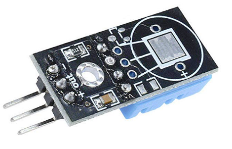
Here is the rear of the sensor:
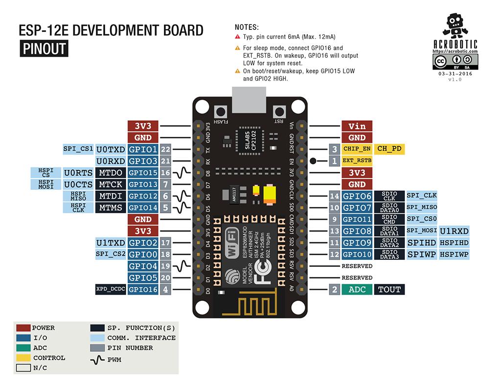
There are three pins: Positive, Negative, and a “data” pin, in the middle. Here is the pinout diagram for the ESP8266:
- Connect the NEGATIVE (” – “) on the DHT11 to a GND pin on the ESP8266.
- Connect the POSITIVE (” + “) on the DHT11 to a 3.3V pin on the ESP8266.
- Connect the middle data “out” pin on the DHT11 to the “GPIO14” pin on the ESP8266. It’s also labeled as “D5” on the board itself.
All three pins are right next to each other, so at least it’s neat, but make sure the connections are right.
Now plug the board into a power source. (Assuming you unplugged it first. Which you should have done.) Then browse to the ESP8266’s web interface. It should look like this:
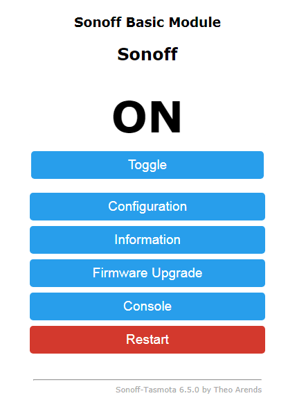
Click on “Configuration” then “Configure Module”. The next part was a little confusing, but this is what it should look like:
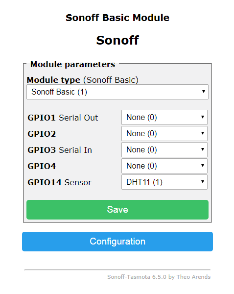
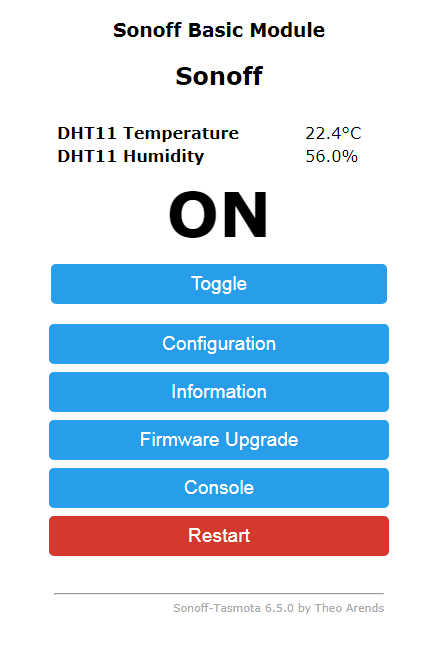
This basically says “connected the GPIO14 pin is a DHT11”. Click “Save” and the device restarts. It should look like this after it reboots:
So, still not much you can do with it, other than check it from the web browser in your phone. The next step will involve getting the ESP8266 to report to some kind of home automation system, such as “HomeAssistant”.
TO BE CONTINUED….