Mango Mini Router – Configuring the LEDs

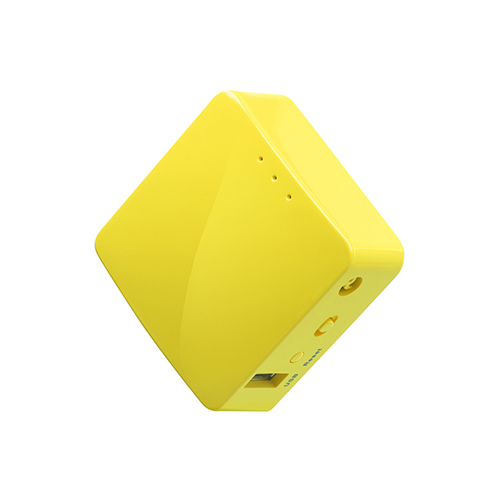
Most people agree that the most important part of any piece of networking equipment is the LEDs. Here I have mapped out how to configure them on the “GLiNet GL-MT300N-V2 Mango Mini Smart Router”.

(This post assumes you have configured your Mango per my previous post.)

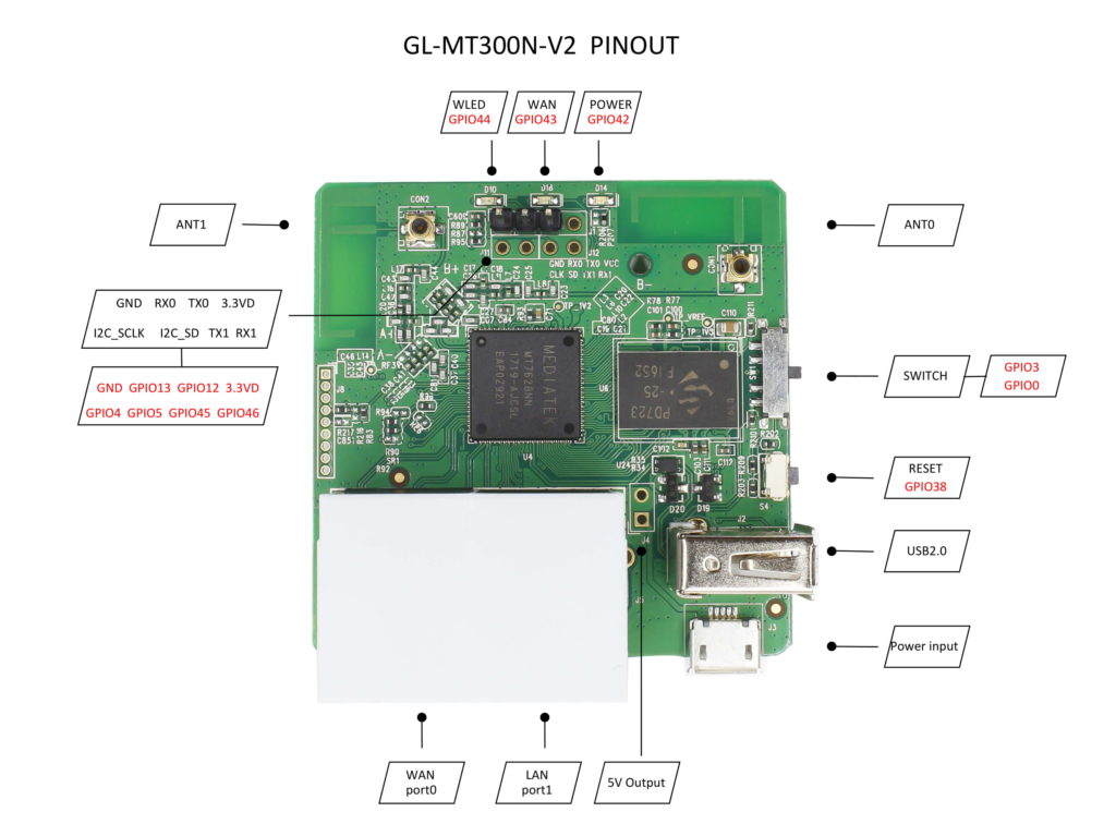
There are four LEDs listed in the router’s user interface:

  • green:power (Top, closest to USB port)
  • green:wan (Middle)
  • red:wlan (Bottom)
  • mt76-phy0 (No idea!)

For reference here are the LEDs in question and how they are referred to in the interface:

Ugh Inkscape why

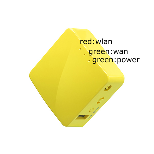
They are all white LEDs. I have no idea why they are labeled as “red” and “green”.

To configure the LEDs, log into the web interface and go to System -> LED Configuration. It will look something like this:

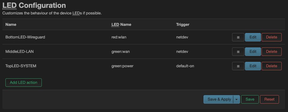
Each row has a “Name”, which you set to whatever you want, the LED name you want to configure (see above), and the “Trigger”:

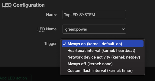
So your options are (not in order):

  • Always on: If the system is booted, it’s on! So it’s a status light for the OS.
  • Always off: If the system is booted, it’s still off! For those that hate fun and whimsy
  • Heartbeat interval: the LED pulses while the system is booted
  • Custom flash interval: It gives you set the time it’s on and off (in milliseconds, so if you want 1 second put in “1000”)
  • Network Device Activity: This is the interesting one.

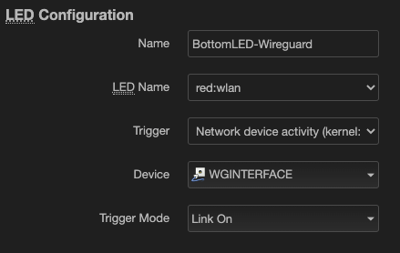
So you can choose which “Device” (interface) you want to use, and the trigger is “Link On” (meaning the interface is online) or transmit/receive (so it flashes as traffic passes through the interface.) In this example it’s “solid on” when the WireGuard interface is up. I have another LED that flashes on activity across the LAN port.

If for some reason you wanted to turn them on via the CLI:

echo 255 > /sys/class/leds/green:power/brightness
echo 255 > /sys/class/leds/green:wan/brightness
echo 255 > /sys/class/leds/red:wlan/brightness
echo 255 > /sys/class/leds/mt76-phy0/brightness

And to turn them off:

echo 0 > /sys/class/leds/green:power/brightness
echo 0 > /sys/class/leds/green:wan/brightness
echo 0 > /sys/class/leds/red:wlan/brightness
echo 0 > /sys/class/leds/mt76-phy0/brightness

Posted in networking | Tagged | Comments Off on Mango Mini Router – Configuring the LEDs

GLiNet GL-MT300N-V2 “Mango” Mini Smart Router – Initial Configuration

I recently found out about and got one of these:

This device is powered via MicroUSB, has a WAN/LAN ports, and can run a wired and wireless network that is connected to the internet via a ethernet cable in the WAN port, another wireless network, or via a “tethered” device connected to the USB-A port.

It comes from the factory with a reskinned old version of OpenWrt. The objective of this post is to document how to replace this with stock OpenWrt and provide an minimal configuration.

Acquire OpenWrt Firmware:

  1. Go to downloads.openwrt.org
  2. Go to the current stable release
  3. “ramips”
  4. “mt76x8”
  5. “glinet_gl-mt300n-v2-squashfs-sysupgrade.bin”
  6. Download the file and make a note of the SHA256 hash
  7. Once downloaded you can verify the hash (on Mac OS it’s “shasum -a 256 <filename> )

Replace Stock Firmware

  1. Take Mango from box
  2. Put Mango “in-line” to your computer such that your computer is connected to the LAN interface and your home network is connected to the WAN interface. Your computer should still be connected to the internet as the stock configuration will work out of the box.
  3. Log into the interface (192.168.8.1)
  4. It will make you select a language and choose a password
  5. Go to the “Upgrade” option on the left and go to the “Local Upgrade” tab
  6. Upload the file you just downloaded by dragging it into the box or browsing to it
  7. Disregard the warnings about unknown firmware
  8. Confirm the SHA256 hash matches
  9. Deselect the “Keep Settings” option
  10. Upgrade
  11. At some point your computer will lose it’s network settings and will be given a new IP address in the 192.168.1.0 range.
  12. Open a new browser window and browse to http://192.168.1.1
  13. Congrats you are now on OpenWrt

Minimal Configuration of OpenWrt

  1. System -> System
    1. General Settings tab
      1. Change the hostname (optional)
      2. Save & Apply
  2. System -> Administration
    1. Router Password tab
      1. Create a Password
      2. Save
    2. SSH Access tab
      1. Interface -> lan
      2. Save & Apply
      3. (I am not an OpenWrt user. But is SSH really accessible to the WAN interface by default? “if unspecified, on all”? Is there a firewall rule in place or something? I might come back to this. There is probably a good reason.)
  3. Network -> Interfaces
    1. Interfaces Tab
    2. Edit the LAN interface
      1. Under the General Settings Tab is where you can change the subnet for your network under the IPv4 address and IPv4 netmask options.
      2. Save
      3. Save & Apply
      4. Open a new browser session and browser to the new IP address (http not https)

Creating a Wireless Network

  1. Network -> Wireless
    1. Edit the “SSID: ” option
    2. Under Interface Configuration
    3. General Setup tab
      1. Change the ESSID to whatever you want
    4. Wireless Security tab
      1. Encryption -> WPA2-PSK
      2. Key -> THISWILLBEYOURWIFIPASSWORD
      3. Save
      4. Save & Apply
      5. (If it still reads as “Wireless is disabled” click “Enable”)

That should be enough to get you off the ground.

Future posts might include

  1. How to get interface to use HTTPS
  2. Use device as VPN Client
  3. Apparently you can chance the behavior of the status LEDs?
  4. What about that switch? Can we change that?
  5. Wait this thing have GPIO pins?
Posted in networking | Tagged | Comments Off on GLiNet GL-MT300N-V2 “Mango” Mini Smart Router – Initial Configuration

Using an Arduino as a TOTP Token

TOTP (time-based One-Time-Passwords) as super neat and widely supported. I will not go into the background or theory, but it is possible to use an Arduino and a RTC module as a TOTP token for your email provider.

DISCLAIMER: STORING YOUR KEY ON AN ARDUINO IS ONLY AS SECURE AS THE PHYSICAL ACCESS TO THE ARDUINO.

The Arduino TOTP library is pretty simple but there are a couple pitfalls:

Your RTC module needs to be set to UTC and fairly close to real time.

If you used the method that I previously posted, you will need to set the timezone on your workstation to UTC. You might also need to set an offset because this method sets the RTC behind your computer because there is a gap between when your computer complies it and when it’s pushed to the RTC.

You could also just add or subtract the appropriate amount of seconds to bring your local time zone to UTC.

You also need to know what format your seed phrase is in.

The string of characters you get from your provider is likely in “Base32”. This Arduino library needs the hex version of a Unicode string. So, if the Base32 string from your provider is this:

JBSWY3DPEHPK3PXP

You need to convert it to Unicode:

Hello!Þ­¾ï

And then convert it to hex in this format:

0x48,0x65,0x6c,0x6c,0x6f,0x21,0xde,0xad,0xbe,0xef

(Ha get it “DEADBEEF”.)

This is all doable using a tool called CyberChef.

This is the bare minimum code needed to return a valid token:

#include <Wire.h>
#include "RTClib.h"
#include <TOTP.h>

RTC_DS3231 rtc;

//Passcode in Base32: JBSWY3DPEHPK3PXP
uint8_t hmacKey[] = {0x48,0x65,0x6c,0x6c,0x6f,0x21,0xde,0xad,0xbe,0xef};

TOTP totp = TOTP(hmacKey, 10);

//Difference in seconds between actual Unix time and what your RTC is saying
int drift = 6;

void setup() {

  Wire.begin();
  Serial.begin(115200);
  delay(1000); // wait for console opening
}

void loop() {
  
    DateTime now = rtc.now();

    char* token = totp.getCode(now.unixtime()+drift);
    Serial.print("TOKEN: ");
    Serial.println(token);

    delay(1000);
}

To verify you can use this website.

From here you can do cool things like give it a battery and OLED display or destroy it because it’s not safe to keep your key lying around.

Posted in Arduino | Tagged | Comments Off on Using an Arduino as a TOTP Token

Arduino: Real-Time Clock Module (DS3231)

Real-Time Clock module running over I2C. You will need to give it a CR2032 battery so it retains the time when the power is removed from the Arduino.

DEVICENANO
GNDGround
VCC+5V/+3.3V
SCLA5
SDAA4

You will need to install the “RTClib” library in the Arduino IDE.

How to Set Time

Before use you need to set the time on the RTC. This script will pull the time from your computer and use it to configure the RTC.

#include <Wire.h>
#include "RTClib.h"

RTC_DS3231 rtc;

void setup() {
  Wire.begin();
  rtc.adjust(DateTime(F(__DATE__), F(__TIME__)));
}

void loop() {

}

This has a couple problems: it uses whatever timezone your computer is using, and it creates a delay of however long it took your computer to compile and upload the sketch (in my case about six seconds.)

How to Read Time

#include <Wire.h>
#include "RTClib.h"

RTC_DS3231 rtc;

void setup() {
  Wire.begin();
  Serial.begin(115200);
}

void loop() {
  
    DateTime now = rtc.now();
    
    Serial.println("Current Date & Time: ");
    Serial.print(now.year(), DEC);
    Serial.print('-');
    Serial.print(now.month(), DEC);
    Serial.print('-');
    Serial.print(now.day(), DEC);
    Serial.print(" ");
    Serial.print(now.hour(), DEC);
    Serial.print(':');
    Serial.print(now.minute(), DEC);
    Serial.print(':');
    Serial.print(now.second(), DEC);
    Serial.println();
    Serial.print("Unix Time: ");
    Serial.println(now.unixtime());
    Serial.println();
    delay(1000);
}
Posted in Arduino | Tagged | Comments Off on Arduino: Real-Time Clock Module (DS3231)

Ducky One 2 – Hot Tips

I recently acquired a tiny hipster mechanical keyboard, the “Ducky one 2 Mini RGB”, a “60% mechanical keyboard” (look it up). After spending a couple hours working out the kinks, I am hereby documenting my findings so I can reference them 3 weeks from now when I forget:

(NOTE: This is not a product review or recommendation. This is a reference for myself and other people who have already bought one and are trying to enjoy it and not regret their decision.)

First of all, to get my Macbook running OS X MacOS to recognize the keyboard I had to update the firmware (which required a Windows computer.)

Upon getting it working, I immediately started to panic because I did not have dedicated arrow keys, which it turns out I use for a lot of things (mainly moving the cursor around which doing word processing or working on command line.) Most keys that were removed in order to make the keyboard smaller are available via “function” key (hereafter “FUN” because that’s what we are having). These include the arrow keys, PageUp, PageDown, Home, and End.

By default there is only one FUN key, on the right side next to the Windows Key. This is not cool because the FUN arrow keys are also on the right. There however is a solution:

Turn CAPSLOCK key into a FUNCTION key:

  1. First make CAPSLOCK is “off”. (so “off” not “ON”)
  2. Press and hold “Fn + Alt + k” for 5 seconds until CAPSLOCK and a couple other keys are illuminated.
  3. By default the CAPSLOCK key should be white. Press it until it turns “indigo”, then hit ESC.
  4. Your CAPSLOCK key should now function as a FUN key.

RGB Backlit Modes

The keyboard also has a bunch of different RGB backlit modes:

  • Rotate Modes: FUN+ALT+T
  • Decrease speed: FUN+ALT+J
  • Increase speed: FUN+ALT+L.
  • Turn off all lighting by holding FUN+ALT+T for 3 seconds.
  • Some of the modes allow you to change the color by using CAPSLOCK + Z, X, or C keys, or CAPSLOCK+SPACE to turn the keyboard into a “palette” from which you can choose a color.

Setting Custom Color Profiles

Custom color profiles are used to set individual keys to specified colors. As far as I know it does not affect or save whatever full keyboard “color mode” you have. You can still change that via FUN+ALT+T. To set custom color profiles:

  1. Hold FUN+ALT+CAPSLOCK for 3 seconds
  2. Select either G (CM1) or B(CM2)
  3. To remove currently preset colors tap the keys you want to un-color.
  4. The CAPSLOCK key will display the currently selected color. You can change the color selected by using CAPSLOCK + Z, X, or C keys, or use CAPSLOCK+SPACE to turn the keyboard into a “palette” from which you can choose a color.
  5. Press the keys you want to set to that color
  6. When you’re done save the custom profile with CAPSLOCK+LEFT SHIFT.

Changing Custom Color Profiles

  1. To change between custom profiles hit FUN+ALT+G or FUN+ALT+B.
  2. If you hit it once it will switch to that profile.
  3. If you hit it again, it will switch to that mode in “breathe” mode.
  4. A third time will turn it off.

While the rest of the internet changed their WASD keys because of the video games, I found it useful to change the FUN arrow keys (I,J,K,L) and the Page-up, Page-down, Home, End, and FUN keys white. Because I am a FUN GUY.

Posted in Uncategorized | Comments Off on Ducky One 2 – Hot Tips

Arduino: Digital Current Sensor (INA219)

Chip which will reach current in a circuit and report it to Arduino via I2C.

DEVICENANOLOADPower Supply
VCC5V
GNDGNDNegative TerminalNegative Terminal
SCLA5
SDAA4
VIN-Positive Terminal
VIN+Positive Terminal

The default I2C address is 0x40. This can be changed by shorting a couple pads, so you could use up to four devices if you wanted.

AddressA0 PadsA1 Pads
0x40OPENOPEN
0x41OPENCLOSED
0x44CLOSEDOPEN
0x45CLOSEDCLOSED

Install the Adafruit INA219 library.

#include <Wire.h>
#include <Adafruit_INA219.h>

#define ina219_addr 0x40;
 
Adafruit_INA219 ina219(ina219_addr);
 
void setup(void) 
{
  ina219.begin();  // Initialize first board (default address 0x40)
}

void loop(void) 
{
  float shuntvoltage = 0;
  float busvoltage = 0;
  float current_mA = 0;
  float loadvoltage = 0;
  float power_mW = 0;

  shuntvoltage = ina219.getShuntVoltage_mV();
  busvoltage = ina219.getBusVoltage_V();
  current_mA = ina219.getCurrent_mA();
  power_mW = ina219.getPower_mW();
  loadvoltage = busvoltage + (shuntvoltage / 1000);
  
  Serial.print("Bus Voltage: "); Serial.print(busvoltage); Serial.println(" V");
  Serial.print("Shunt Vo: "); Serial.print(shuntvoltage); Serial.println(" mV");
  Serial.print("Load Volt: "); Serial.print(loadvoltage); Serial.println(" V");
  Serial.print("Current: "); Serial.print(current_mA); Serial.println(" mA");
  Serial.print("Power: "); Serial.print(power_mW); Serial.println(" mW");
  Serial.println("");

  delay(2000);
}

From Adafruit’s documentation:

float getBusVoltage_V(void);  
Reads the voltage between GND and V-.  This is the total voltage seen by the circuit under test.  (Supply voltage – shunt voltage).  

The return value is in Volts.

float getShuntVoltage_mV(void);  
Reads the voltage between V- and V+.  This is the measured voltage drop across the shunt resistor.  

The return value is in Milivolts.

float getCurrent_mA(void);
Reads the current, derived via Ohms Law from the measured shunt voltage.

The return value is in Milliamps.

Posted in Arduino | Tagged | Comments Off on Arduino: Digital Current Sensor (INA219)

WLED – Macros

I have been using the “WLED” project running on an ESP8266 to power a strip of individually controlled LEDs in my house. It works pretty well, except I don’t like have to use the web interface to turn it on and off. So I am currently working on a “remote control” which will use a second ESP8266 to send commands to the controller over Wifi and HTTP.

These “commands” look like this:

T=0POWER OFF
T=1POWER ON
T=2TOGGLE POWER
PL=1Use Preset #1
M=1Use Macro #1

A list of full commands can be found here:

https://github.com/Aircoookie/WLED/wiki/HTTP-request-API

These commands can be sent over the HTTP like this:

http://1.2.3.4/win&T=2

Or entered into a pre-defined Macro box:

Not my screenshot

In this example, they have saved the command “T=1” into Macro Slot #1.

These macros (and subsequent command) can be called via the HTTP API like this:

http://1.2.3.4/win&M=1

My current idea is to create a program running on a ESP8266 with three push buttons attached that will send the command to use Preset 1, Preset 2, or turn off based on the pressing of one of the three buttons.

Posted in ESP, Home Automation | Tagged , | Comments Off on WLED – Macros

Inserting Magnets into 3D Prints

3D printing magnets has been one of my favorite projects. Not the actual magnetized metal, but tacky placards to hang on your fridge or cubicle.

For Christmas many years ago someone gave me a bunch of small magnets (these happen to be 3.2mm cubed). So far in my magnets I have been leaving holes in the bottom and hot gluing them in. But this is messy and the magnets tend to be left behind after a while. I wanted to try embedding them inside the print itself, which would be pausing the print at a specific height, dropping the magnets in, and restarting the print.

I wasn’t sure how much material to leave between the magnet and underside of the printed object, so I designed a test object:

The top row was for testing dimensions of the cavity to leave for the magnet. The bottom two rows tested how much materials to leave between the bottom of the magnet and the underside of the print:

3.2mm x 3.2mm3.6mm x 3.6mm4mm x 4mm
0.2mm Floor0.4mm Floor0.6mm Floor
0.8mm Floor1.0mm Floor1.2mm Floor

These measurements were chosen because I am normally using a 0.4mm nozzle, laying down 0.2mm layers.

The 3.6mm….void…. was the best fitting, but a little loose. 3.4mm might be better but I am not sure how that would work based on the nozzle size. After printing one in 3.6mm I might go down as you could hear the magnets rattle when object was shaken shook done shook.

The magnet was able to hold up the test piece on all six options, but as expected, the strength of the hold weakened as more material/distance was added. I think the 0.4mm floor was the best compromise between strength of the hold and strength of the print.

Turns out this is super easy to do in PrusaSlicer. Just move to the appropriate layer (the one right before the magnet voids are covered up), right-click on the “+” sign and “add pause print (M601)”. This will pause the print when it gets to that layer height so you can add your magnets (make sure the polarity is correct!). Once you are done, unpause the print from the printer.

Posted in 3DPrinting | Tagged | Comments Off on Inserting Magnets into 3D Prints

3D Printing Text

Printing objects with different color text is a pretty neat effect (see previous post regarding printing with multiple colors.) You do have to be careful with the size of the letters though, as they quickly lose definition. The following are three versions of a faceplate for an overly complicated benchtop power supply I put together:

Letter height was measured with calipers, so it might not actually be what I selected in Fusion360.

The lettering on the first one looked pretty crappy. For the second version I switched to a 0.25mm nozzle, so I was able to get much better definition but it took for-ev-er.

For some reason my final print didn’t have the vent holes I painstakingly designed by hand.

Also I hadn’t installed the USB port when I took this picture. I have since installed it and it looks dope.

I ended up having to reprint it a third time because the components didn’t fit right. At the same time I also made the letters even bigger and switched back to a 0.4mm nozzle. The final version had 8mm and 11mm lettering according to Fusion 360.

CONCLUSION

On a 0.4mm nozzle, don’t go smaller than 8mm height. When using a 0.25mm nozzle, don’t go smaller than 5mm. This also depends on your font. I was using big chunky letters, so if you used something more delicate you would have to go even bigger, or use the smaller nozzle.

BONUS CONTENT

If you print something flat-ish, leave it on the print bed until everything has cooled down to room temperature. I took the faceplates and the body of the power supply off too early and they warped pretty badly.

Posted in 3DPrinting | Tagged | Comments Off on 3D Printing Text

Arduino: OLED Display (SSD1306)

The ones I got were 126×64 displays powered by SSD1306 chips. They run over I2C so they are pretty easy to wire up:

DEVICENANO
GNDGround
VCC+5V
SCLA5
SDAA4

You do have to make sure you have the right I2C address in your code. For some reason mine were labeled as using “0x78” but were actually “0x3C”. (Thanks, anonymous Amazon reviewer!)

As far as code, it’s pretty easy to use the Adafruit SSD1306 and Adafruit GFX libraries. But for my purposes it was too resource intensive so I found an ASCII only library.

// Demo of ASCII only OLED library
#include <Wire.h>
#include "SSD1306Ascii.h"
#include "SSD1306AsciiWire.h"

//Configure Screen
#define SCREEN_WIDTH 128 // OLED display width, in pixels
#define SCREEN_HEIGHT 64 // OLED display height, in pixels
#define I2C_ADDRESS 0x3C
#define RST_PIN -1
SSD1306AsciiWire oled;

void setup() {
    Wire.begin();
    oled.begin(&Adafruit128x64, I2C_ADDRESS);
    oled.setFont(System5x7);
    oled.clear();    
}

void loop() {
      oled.setCursor(0, 0);
      oled.print("TEXT GOES HERE");
      delay(1000);      
}

To move text to different parts of the screen use “oled.setCursor(column,row);” My displays have 8 rows (0-7) with the default text size. Each character is approximately 5 pixels wide.

If you want to make the text bigger you can use “oled.set2X();” before your “oled.print” statement.

UPDATE:

If you want to use a 128×32 display use the following portions of code:

#define SCREEN_WIDTH 128 // OLED display width, in pixels
#define SCREEN_HEIGHT 32 // OLED display height, in pixels

oled.begin(&Adafruit128x32, I2C_ADDRESS);


Posted in Arduino | Tagged | Comments Off on Arduino: OLED Display (SSD1306)