Opens and closes a circuit that’s “air-gapped” from the Arduino, allowing you to open/close circuits of much higher voltages (like 120V). Not sure how how good of an idea that is, considering the quality of these boards.
DEVICE
NANO
DC+
+5V
DC-
Ground
IN
D2
On the other side, “COM” is the positive “input”. “NO” is “normally open” and “NC” is “normally closed”.
//Opens and closes relay

#define RELAY_PIN 2     // Sets pin connect to relay as D2

void setup() {
  // initialize digital pin 9 as an output.
  pinMode(RELAY_PIN, OUTPUT);
}

void loop() {
  digitalWrite(RELAY_PIN, HIGH);
  delay(1000);
  digitalWrite(RELAY_PIN, LOW);
  delay(1000);
}
Posted inArduino|Taggedarduino|Comments Off on Arduino: Relays
It operates as any other momentary switch (in that it “closes” when you are touching it, and “opens” when you let go. As opposed to “toggling” between “on” and “off.”)
DEVICE
NANO
VCC
+5V
GND
Ground
SIG
D2
On these Nanos, pin 13 is the built-in LED, so you don’t have to wire in anything else.
//Demonstrating Capacitive Touch Switch (TTP223B) on Arduino Nano

int ledPin = 13;
int touchPin = 2;

void setup() {
  Serial.begin(9600);
  pinMode(ledPin, OUTPUT);
  pinMode(touchPin, INPUT);
}

void loop() {
  int touchValue = digitalRead(touchPin);

  if (touchValue == HIGH) {
    Serial.println("TOUCHED");
    digitalWrite(ledPin, HIGH);
  }
  else {
    digitalWrite(ledPin, LOW);
  }
}
Posted inArduino|Taggedarduino|Comments Off on Arduino: Capacitive Touch Switch (TTP223B)
I recently bought some Arduino Nano clones. The clones are vastly cheaper, but they are clearly not as well made, and sometimes you might end up with slightly different versions of things. The official Arduinos also help fund the Arduino project, which is good for everyone.
If you are just getting started I would recommend getting a real one so you know it’s going to work and the documentation is correct.
Anyway, for my own documentation, these are the settings I needed to get it working:
Board: Arduino Nano
Processor: ATmega328P (Old Bootloader)
Built-in LED: 13
SDA: A4
SCL: A5
Here is the official pinout diagram for the Arduino Nano:
I like Rasperry Pi’s, but they have one glaring problem:
There is no way to shut them down.
I run all of mine as servers, so if I can’t access them over the network you can’t press a button on them and have them shut down, you have to pull out the power cable. Which in my experience ruins the SD card.
However there is a way to boot off a USB storage device instead. I am linking to the official documentation here WHICH YOU SHOULD DEFINITELY READ:
It is possible to create 3D prints with multiple colors. This is done by swapping out filaments at different points in the prints. You can use something like the Prusa MMU to create prints with multiple colors on a single layer, but this requires more hardware and it’s pretty time intensive, buggy, and wasteful.
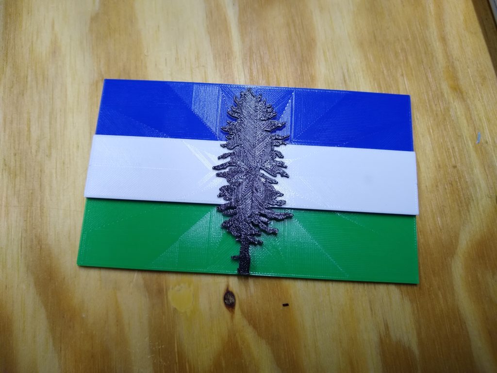
It is also possible to create multicolor prints by swapping the filament in between layers, so you could have a background that is one color and an image sitting on top of it that is a different color. This is possible with a feature in the stock Prusa Slicer, which I will document here, using this as an example:
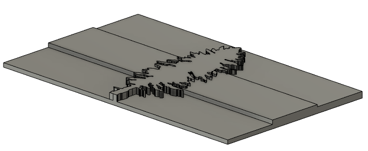
Step 1: Create STL
Find and import SVG into Fusion360 and extruding the parts you want to be different colors to different heights. (Wikipedia seems to be a pretty good source for this.) For example:
Extrusion Heights:
You’ll want to do it in multiples (increments?) of your layer height. So don’t do 1.5mm with a 0.2mm layer height, for example.
Bottom Section (Green): 2mm
Top Section (Blue): 3mm
Middle Section (White): 4mm
Tree (Black): 5mm
Import STL in Prusa Slicer. I used these settings:
0.2mm Layer Height
25% Infill
Brim
Everything else was default, include top/bottom horizontal layers
70°C for bed because I am printing in cold conditions and I was having problems with adhesion.
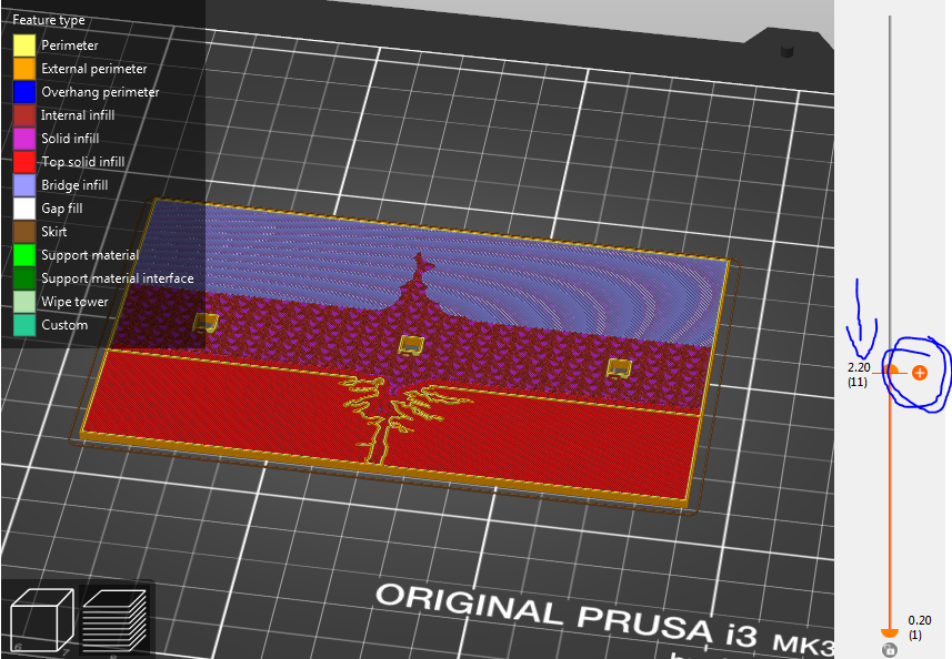
Click over to the “Preview” pane. Move the slider on the right so where you want to the layer change to occur. The number on the left is the height in millimeters at that time, and the number under that is the layer number. Click the “+” on the right to add a color change.
By adding color changes to a print, PrusaSlicer is adding an “M600” instruction to the GCODE at the specificed layer. When a Prusa printer hits the M600, it will move the print head out of the way and eject the filament, then prompt you to manually swap the filament. (It will also start beeping, so probably don’t want to let it wait while you are at work.)
At this point you will pull out the old filament, and push the new filament ALL THE WAY TO THE EXTRUDER. If you have an MMU, this command will not interact with the MMU at all. You will have to push the new filament all the way through the MMU body to the extruder. Once it’s in there, press the button and and it will have you confirm it’s extruding, then resume printing.
The following point is the whole reason I am writing this:
THIS PAUSE-AND-SWAP OCCURS BEFORE THE SELECTED LAYER BEGINS.
So if you want the layer at 2mm to be white, and everything above 2mm to be black, put at color change AT THE NEXT LAYER ABOVE 2MM.
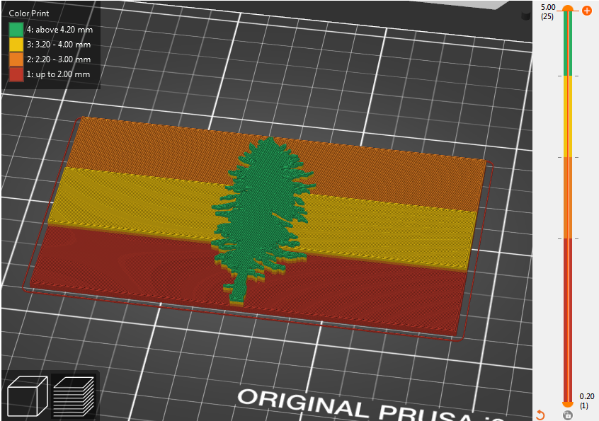
So in my example, this is what it looked like in Prusa Slicer:
With Color Changes at:
2.2mm (Remove Green, Insert Blue)
3.2mm (Remove Blue, Insert White)
4.2mm (Remove White, Insert Black)
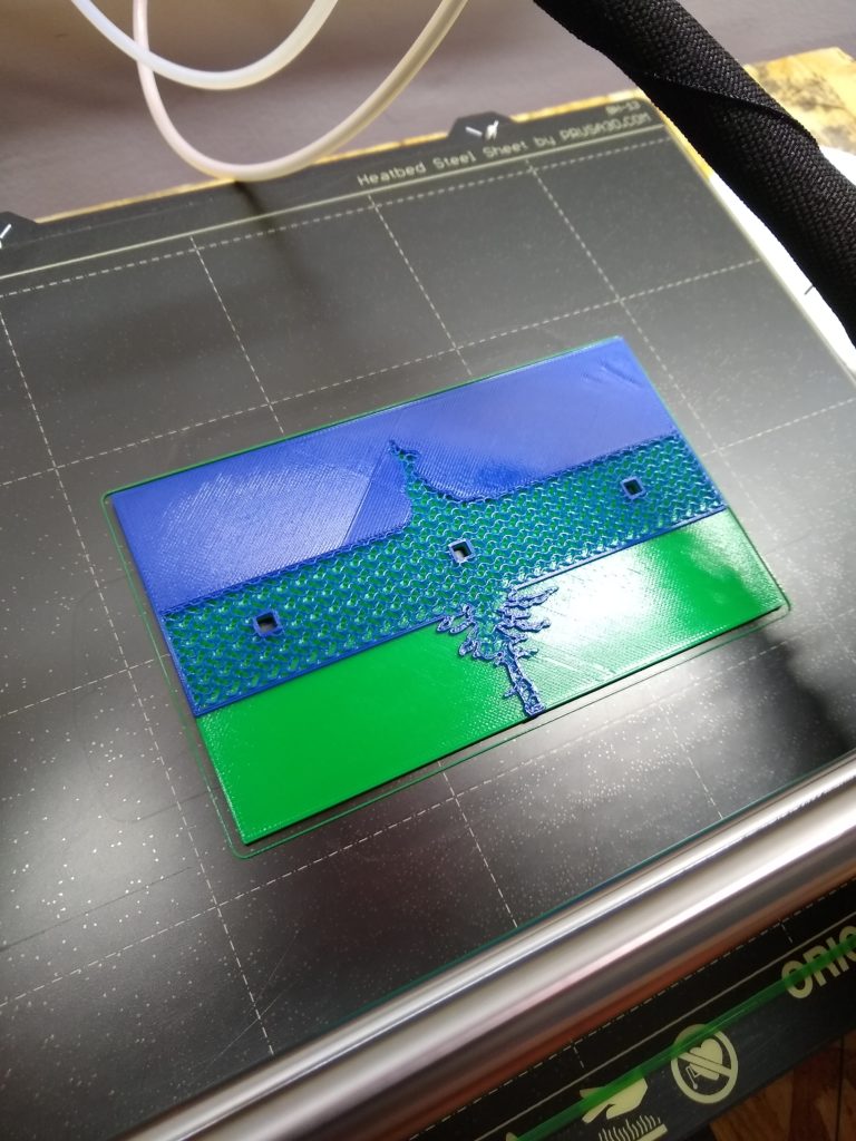
Mid-Print:
Final Product:
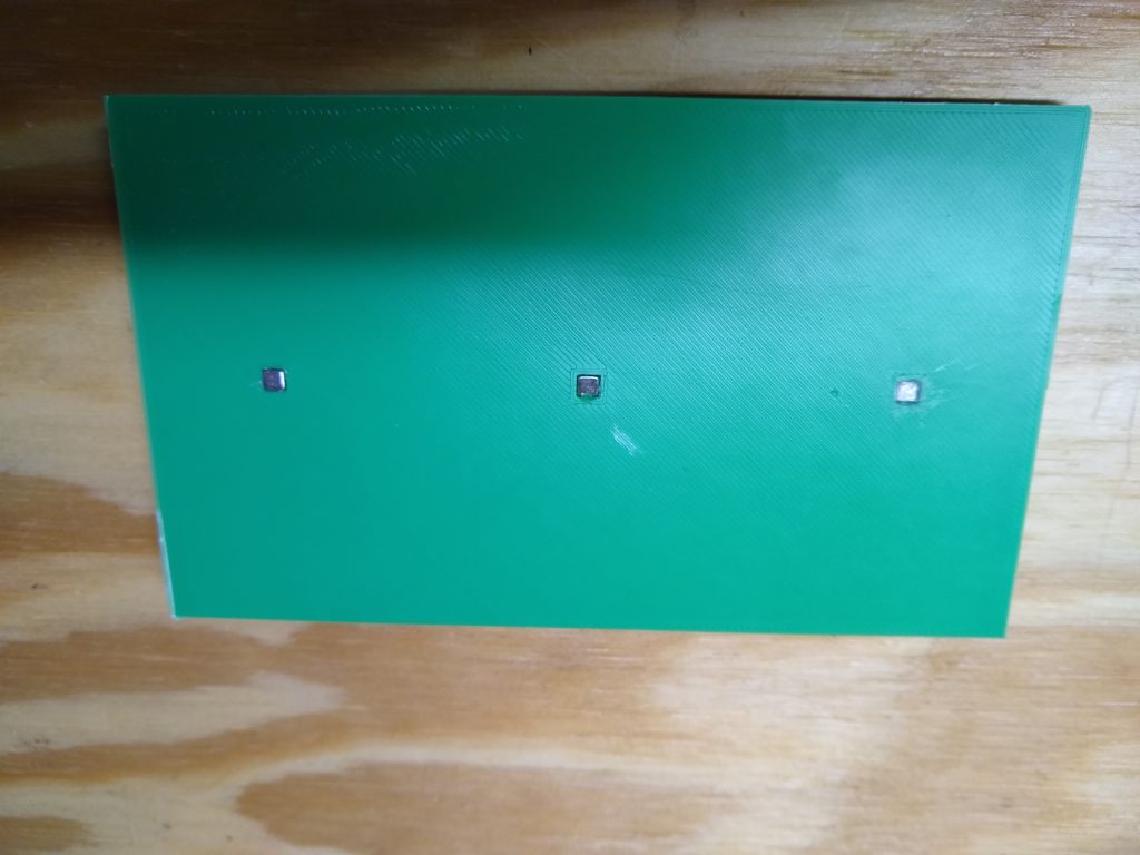
Reverse with embedded magnets:
Final Thoughts:
This ended up coming out pretty well. Prusa is adding in the ability to swap filaments at the layer change in the next release of Prusa Slicer, so that will make it easier.
So I originally intended this to be one of my first posts, but I thought it was a little unnecessary given the vast amount of information already out there explaining in more detail and with greater accuracy the same topic. But since I already typed it up, let’s go for it.
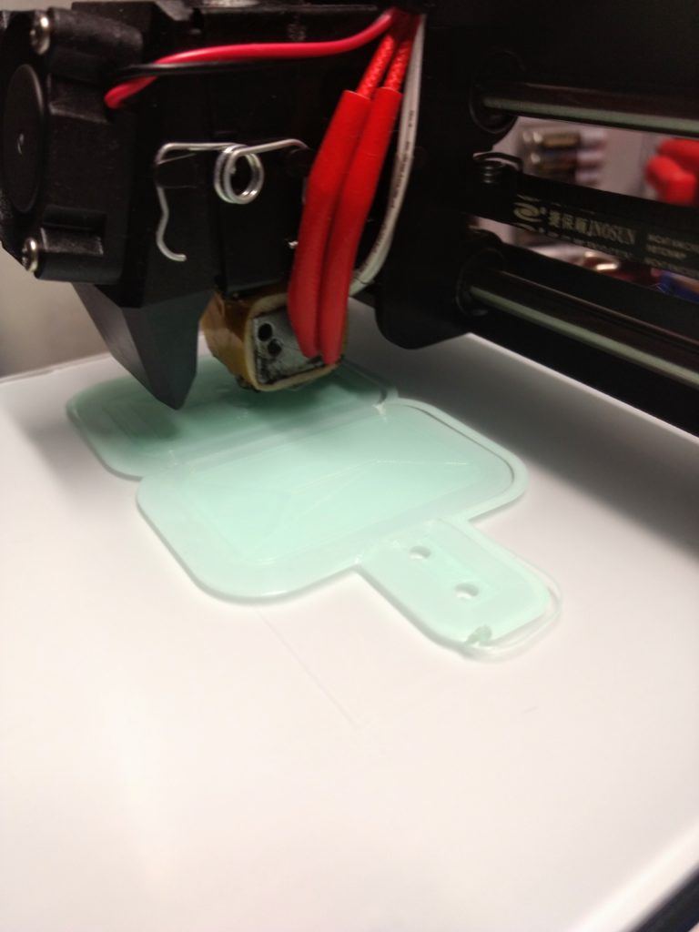
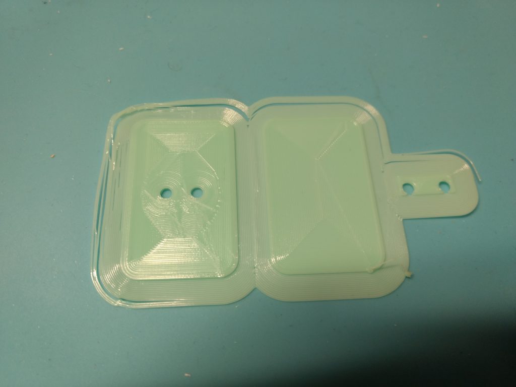
There are several different kinds of 3D printers. The most basic and common these days are “FDM” printers (“fused deposition modeling”). This kind of printer forces a special kind of plastic through a tiny headed nozzle as it moves the nozzle in a specified pattern, which leaves a trail of oozed plastic behind it. When it has finished with that pattern, it moves the nozzle up a tiny amount, then moves in a different pattern, leaving a new trail of oozed plastic on top of the previous layer. This process builds a three-dimensional object, layer by layer, starting from the bottom.
There are many different kinds of plastic you can use in these printers. The one most people start with is called “PLA.” It prints pretty easy and does not produce any toxic fumes (AS FAR AS I KNOW. I let mine run in the garage.)
All 3D prints start with a 3D image file (“.stl”). You can download them from a repository like Thingiverse or make them yourself in a 3D modeling program. When you find an object you want to print, you import the STL of that file into a program called a “slicer”, such as Cura or “Slic3r”. After tweaking some settings, you export a different kind of file called a “GCODE” file, which is basically a text file that contains all the commands for the printer to run, step by step, to construct the object in the STL file. This include commands to move the print head on all three axis, heat up the bed or extrude, or actually extrude the filament. Once all the printer runs all the commands, you can pry your part off the build plate. That’s it. END OF PRIMER.
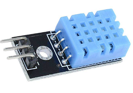
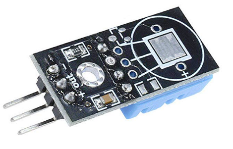
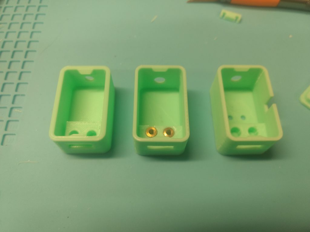
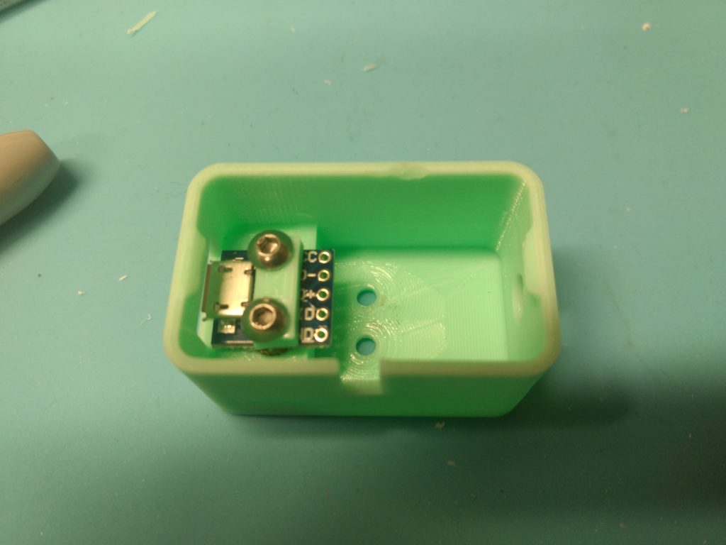
So my goal in this project is to create a network of temperature and humidity sensors, using the ESP8266’s. To facilitate this I purchases a pack of these sensors:
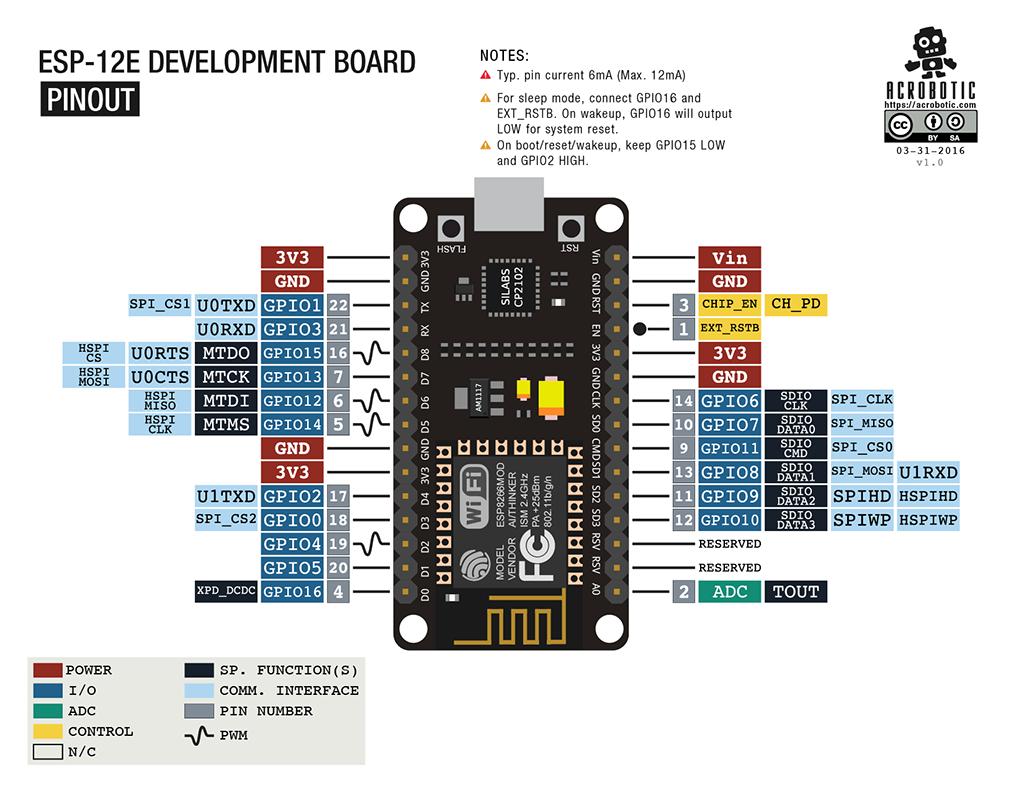
There are three pins: Positive, Negative, and a “data” pin, in the middle. Here is the pinout diagram for the ESP8266:
If you click the image is should open a bigger version in a new tab.
Connect the NEGATIVE (” – “) on the DHT11 to a GND pin on the ESP8266.
Connect the POSITIVE (” + “) on the DHT11 to a 3.3V pin on the ESP8266.
Connect the middle data “out” pin on the DHT11 to the “GPIO14” pin on the ESP8266. It’s also labeled as “D5” on the board itself.
All three pins are right next to each other, so at least it’s neat, but make sure the connections are right.
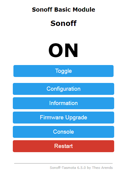
Now plug the board into a power source. (Assuming you unplugged it first. Which you should have done.) Then browse to the ESP8266’s web interface. It should look like this:
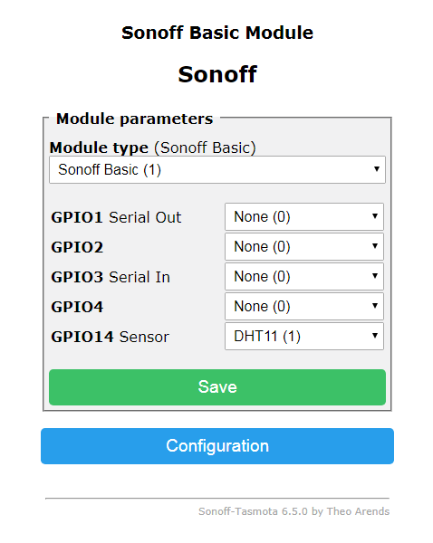
Click on “Configuration” then “Configure Module”. The next part was a little confusing, but this is what it should look like:
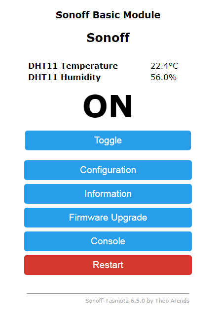
This basically says “connected the GPIO14 pin is a DHT11”. Click “Save” and the device restarts. It should look like this after it reboots:
Oh shit Celsius
So, still not much you can do with it, other than check it from the web browser in your phone. The next step will involve getting the ESP8266 to report to some kind of home automation system, such as “HomeAssistant”.
I was recently sent a NodeMCU ESP8266 by some rando on the Internet. According to Wikipedia “the ESP8266 is a low-cost Wi-Fi microchip with full TCP/IP stack and microcontroller capability.” It’s basically an Arduino with WiFi. And they are like $7 online. I ordered a few more off Amazon once I got the first one working. These were the ones I ordered:
There are a bunch of different hardware versions so just be careful which one you are getting.
The same friend rando that sent me the board suggested I start with something called “Sonoff-Tasmota” which the Github page describes in the following manner:
Alternative firmware for ESP8266 based devices like iTeadSonoff with web UI, rules and timers, OTA updates, custom device templates and sensor support. Allows control over MQTT, HTTP, Serial and KNX for integrations with smart home systems. Written for Arduino IDE and PlatformIO.
Here are some super quick instructions to get you started (also courtesy of the same friend rando):
DO THIS AT YOUR OWN RISK. IF YOU DON’T UNDERSTAND WHAT’S HAPPENING, STOP AND LOOK IT UP.
Install Python on computer
Run “Pip install esptool”
Download “sonoff.bin” in esptool directory
Put NodeMCU into “flash mode” by holding down flash button while plugging into your computer via USB
Run this command:
esptool.py.exe –port COM5 write_flash -fm dio 0x00000 sonoff.bin
Restart the NodeMCU by unplugging and replugging
Use something like Putty to serial into the device on Com5 using buad rate 115200. This will tell you the IP address
When the device reboots it will create a Wifi access points which you can connect to, then browse to the IP address you learned in the previous step. It takes you to a page where you can give it the SSID and password to connect it to your actual network.
FUN NOTE: Both your SSID and password will be sent to the NodeMCU in cleartext, for any one sniffing all the unencrypted Wifi in the area.
Okay, so originally I was configuring these over unsecured Wifi, but I found a better way to get it on your network:
After you flash the device, restart by unplugging and replugging
Connect via serial (I used the Arduino IDE) with the correct COM port and set the BUAD rate to 115200.
Enter in the following command through the serial interface:
These things were so awesome I had to start another blog to talk about it. (It’s this blog. This is the one I started.)
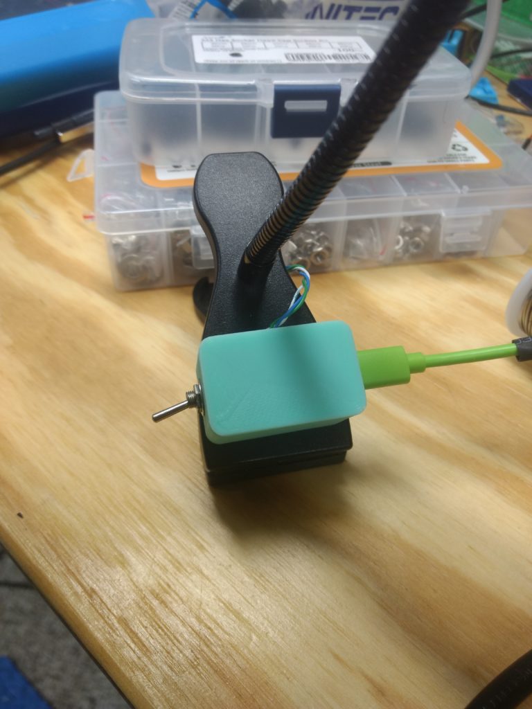
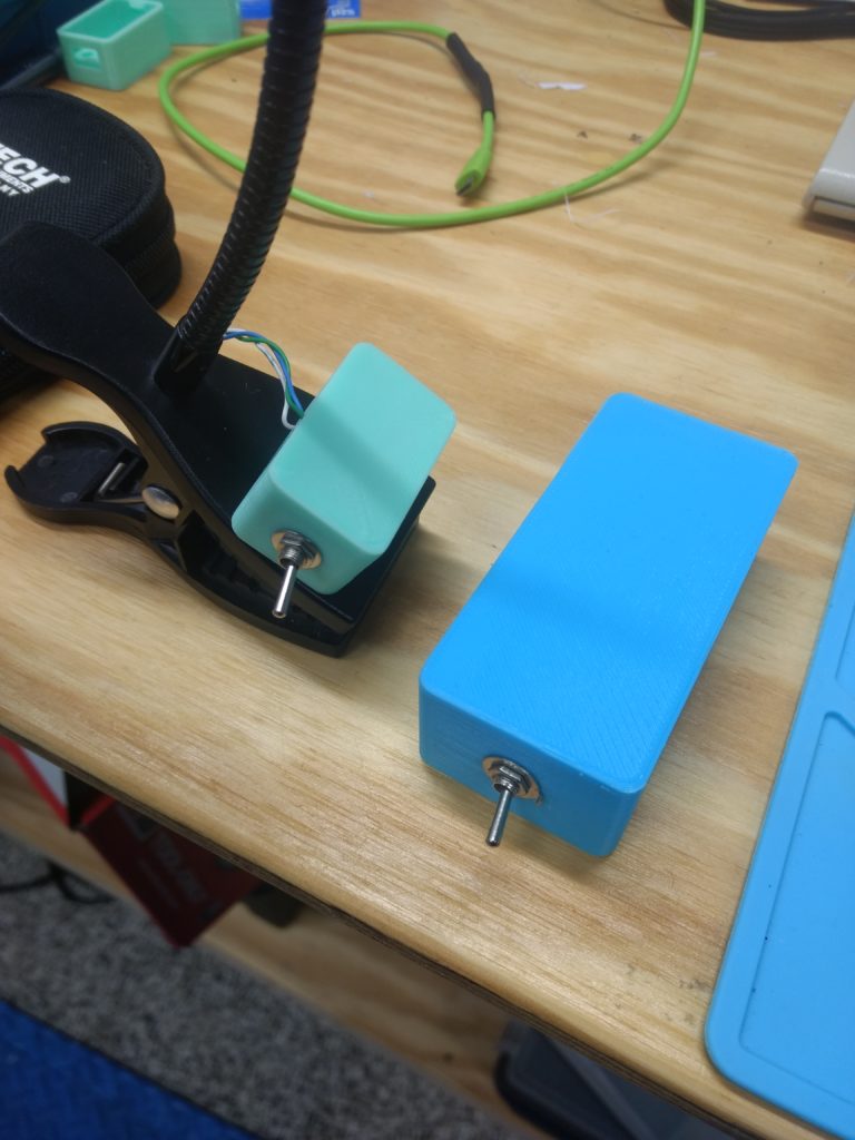
Behold!
Wait hold on…
Behold!
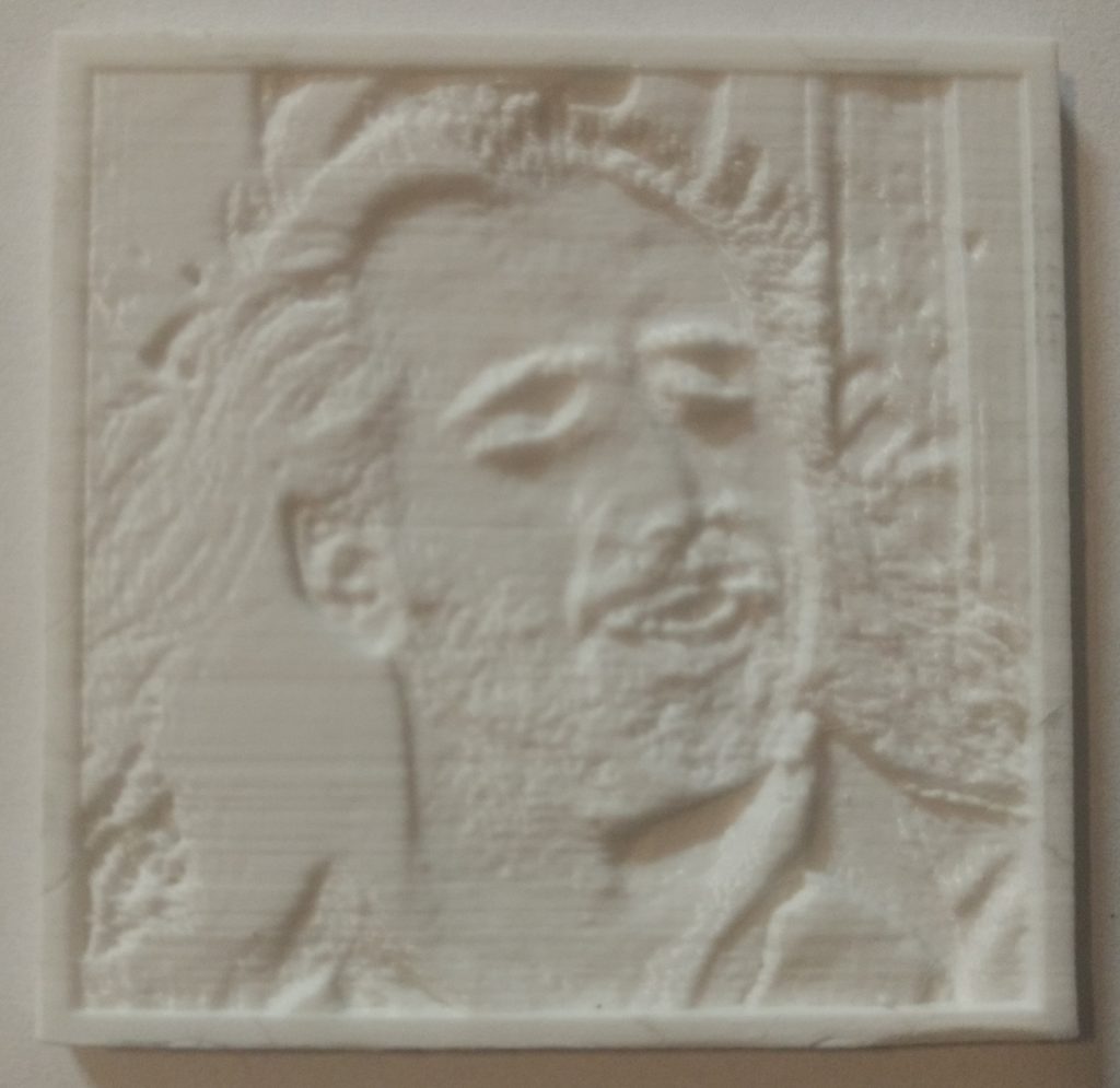
These are 50mm square 3D-printed lithophanes. A lithophane is an object that uses the variable thickness of the material to create a two-dimensional image. Basically there is more material on “darker” parts of the image, which results is less light being able to shine through. This is the awesome website I used:
I have been playing around with these for a few weeks now and I wanted to run some “tests” to see if certain settings affected the print quality. The three things I tested were:
Layer Height (0.0875 vs 0.1313, smaller height means more detail but longer print time (These heights are specific to this printer!))
Number printed at once (does the printer skipping around printing a bunch at once create weird layers or anything)
Orientation (Flat on bed vs Vertical)
For all the tests I used a Monoprice Select Mini V2 using white Hatchbox PLA and the same STL file.
Website Settings
Model Settings
Maximum Size: 50mm
Thickness: 3mm
Border: 2 mm
Thinnest layer: 0.8mm
Image Settings
Set to POSITIVE IMAGE
The other settings I left as-is.
Printer (Cura) Settings
Hotend Temp: 205
Bed Temp: 60
Infill: 100%
Retraction Distance: 7mm
Retraction Speed: 30 mm/s
Print Speed: 50mm/s
Support: None
Adhesion: Brim, 12mm
In order to be scientific and whatnot I printing NINE of these. For YOU:
Print Number
Test Variables
No. 1
Only one printed, vertical, Layer Height: 0.0875
No. 2-4
Three printed simultaneously, vertical, Layer Height 0.0875
No. 5
Only one printed, horizontal (flat on bed) Layer Height 0.0875
No. 6-9
Four printed simultaneously, vertical, Layer Height 0.1313
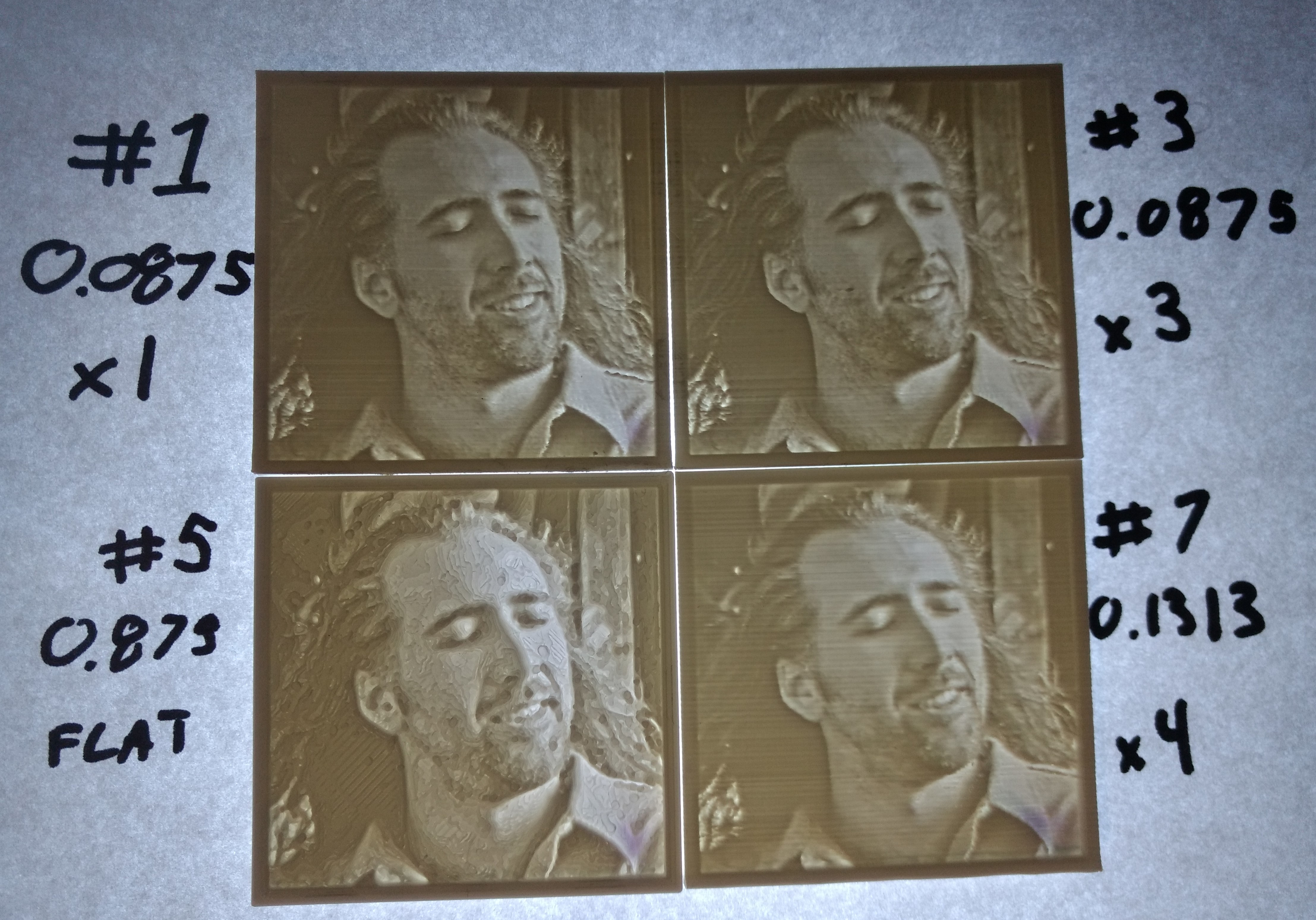
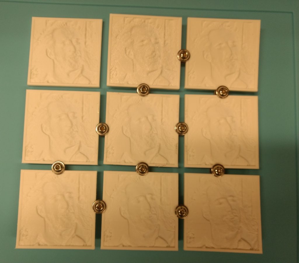
And here are the results:
I think if you click on the image it will open a bigger copy for inspection.
This is after minimal post-print processing, I basically just trimmed excess off the edges.
For starters, #5 looks nuts. It’s actually kind of a cool effect. This is the one that was printed flat on the bed. I read beforehand that you’re supposed to print them vertically because the X and Y axis are capable of much finer details. Or something to that effect.
#7 looks obviously worse than #1 and #3. This is due to the layer height being double the others. On the other hand, it printed twice as quickly.
I think it’s a toss-up between #1 and #3 as far as quality of print. While the print run for the #3 was three times as long as #1, it also gave me three copies, which saved me time not having to reset the printer and whatnot (I think it was like 8 hours?). There is a tiny blob on his cheek that is not there on the other prints from that run (#2 or #4) but who’s to say that is a product of three printing simultaneously.