
I bought an Ikea reading light several years ago to use for reading in bed before going to sleep. It was brought to my attention that it was SUPER, UNNECESSARILY bright for a pre-bed reading light. Which I can’t say I disagreed with. I had also read that “amber” colored light is best for helping brains prepare for sleep. So I decided to make my own reading lamp, based on parts I had lying around, namely a “micro” form-factor Arduino and an “RGB” LED from Adafruit. Basically an “RGB” LED is an LED with three seperate diodes inside of it – a red one, green one, and blue one (hence “RGB”). Based on what color you want it to emit, you control how much voltage to apply to each of the terminals. This was accomplished pretty simply with the Arduino, which conveniently ran off MicroUSB.
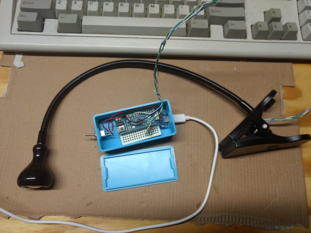
Initially it all ran off a breadboard rubber-banded to a piece of cardboard, and used a tiny lamp enclosure I made out of some aluminum foil and cardboard. I eventually figured out that I could put the new LED into the Ikea reading lamp enclosure, after running new wires up the neck (which was a big pain, I ended up using 2 pairs of wire from inside a CAT5 cable.) I also bought a project box to house all of the components, which I eventually replaced with a custom box I designing and 3D printed:
That’s all to say that now that I understand how LEDs work, I think I can make a new one simply with resistors, (hereafter “MkII”) Let’s try:
These LEDs have four “legs” FINGERS (oriented as if you are looking at the palm of your hand like you just wrote something on it). The below details were painstaking gathered from the supplied datasheet:
| PIN | DISPLAYED COLOR | FORWARD VOLTAGE | |
| Index Finger | RED | 1.8V | |
| Middle Finger (The long pin) | Common Ground (But actually goes to positive terminal) | N/A | |
| Ring Finger | GREEN | 3.2V | |
| Pinkie | BLUE | 3.2V |
FUN NOTE: The Adafruit product page lists much different Forward Voltages than the datasheet!
Based on an “RGB Calculator” I found online just now, the color amber I just picked out is “EFEF00” which translates to 93% red, 93% green, and 0% blue. So let’s trying applying 93% of the power to the red and green pins and none to the blue
Based on the math from the previous post we need to apply 172Ω of resistance to the red pin and 97Ω to the green (and nothing to the blue.) For the red pin, we can get to 172Ω by putting a 100Ω, 47Ω , and 20Ω resistor in series. We’ll just round up to 100Ω for the green.
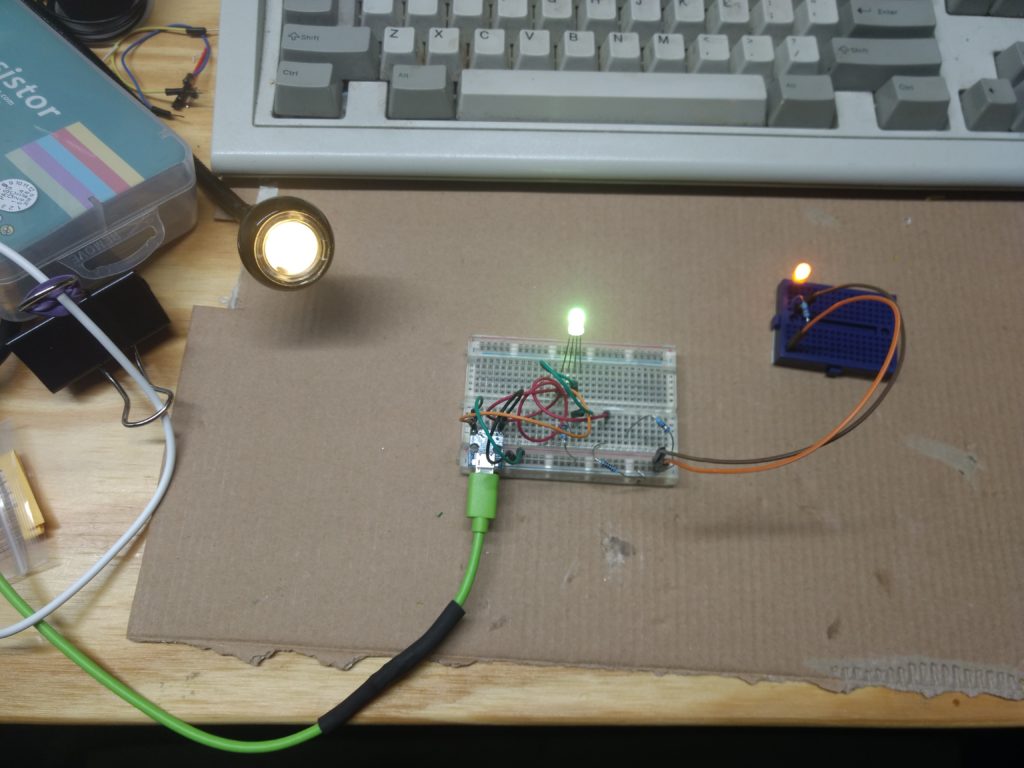
Above is the MkI on the left, the MkII configuration described above in the middle, and on the right was a regular yellow LED I had on hand. As you can see the light in the middle is a lime green. After some trial and error I found the a nice amber color using a 100Ω resistor for the green pin and a 47Ω resistor for the red pin. Go figure.
So now we know how to replace the entire functionality of the Arduino in the MkI with two resistors for the MkII.
I could probably reuse the MkI enclosure but one of the pegs holding the microUSB breakout board broke off, which means I can’t plug and unplug the whole thing as I originally desired. So I will probably just redesign the whole box. Onward!