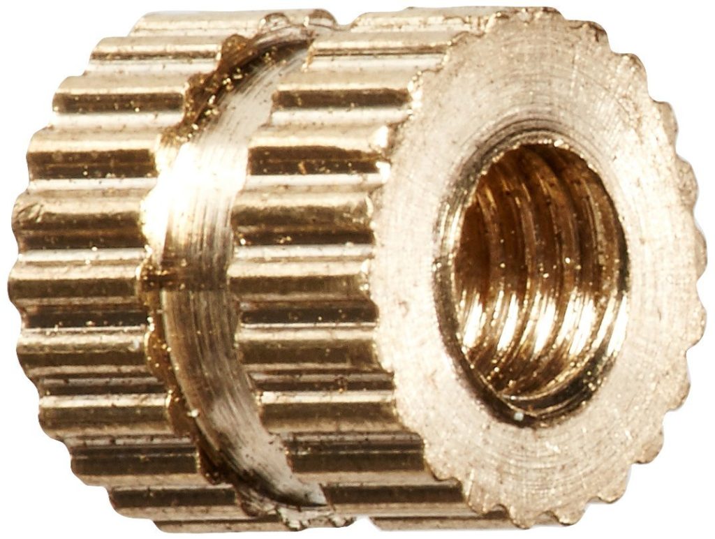
I read about using them on 3D printed projects and thought I would try them, so I ordered a bag of 100 off Amazon (these specifically). These specific ones are “M3 x 5mm x 5.3mm ” which means they are designed for M3 standard bolts, are 5mm deep and 5.3mm wide.
Side Note: If you are going to be designing projects and printing them I highly recommend getting a box of assorted M3 bolts/nuts (I also have a box of M3 through M6 which I have used.) Available on Amazon!
This is how they work:
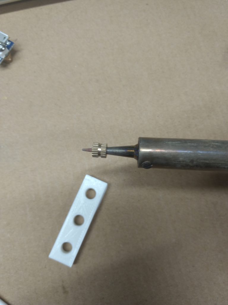
You print something that has a hole approximately 5mm (or more) deep and 5.3mm wide. At first I wasn’t sure about exactly how wide the hole needed to be so I printed a test board that had three holes (5.3mm, 5.35mm, and 5.4mm).
Sloppy but functional.
Then you heat up your soldering iron, put the insert onto the end, give it a second, then carefully push the insert/soldering iron into the hole.
I didn’t take any pictures of that last step because I needed both hands. It turns out my precise measurements did not matter AT ALL as PLA melts SUPER EASILY, as that is it’s entire purpose.
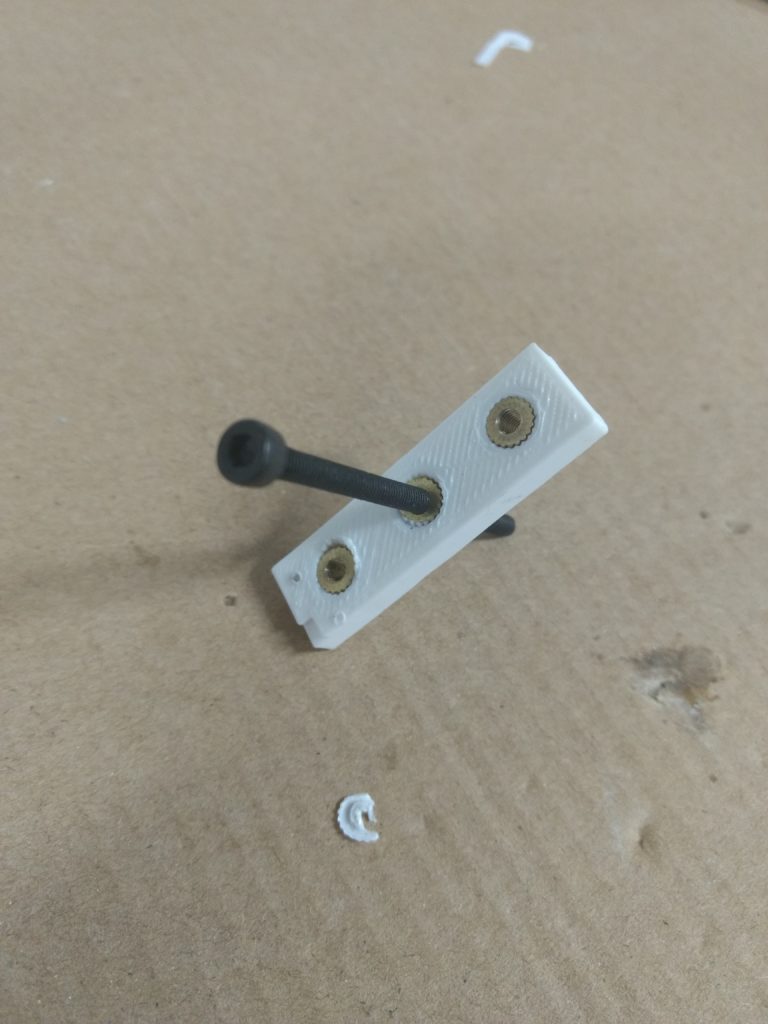
I managed to get all three in passably well, but I am glad I practiced because I could definitely see messing up an entire print by trying to insert these suckers. The trick is to remove the soldering iron from the insert as soon as it is in while leaving in the insert (I used needlenose pliers). It is shocking (well maybe not) how quickly the entire thing started to soften and melt with the soldering iron in place.
I will probably be using these for the MkII reading lamp, as they are cool and I like them.
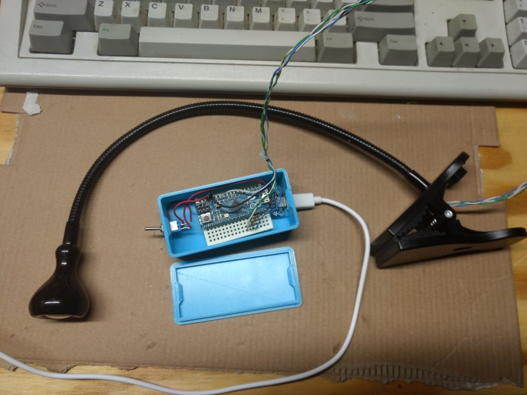
I bought an Ikea reading light several years ago to use for reading in bed before going to sleep. It was brought to my attention that it was SUPER, UNNECESSARILY bright for a pre-bed reading light. Which I can’t say I disagreed with. I had also read that “amber” colored light is best for helping brains prepare for sleep. So I decided to make my own reading lamp, based on parts I had lying around, namely a “micro” form-factor Arduino and an “RGB” LED from Adafruit. Basically an “RGB” LED is an LED with three seperate diodes inside of it – a red one, green one, and blue one (hence “RGB”). Based on what color you want it to emit, you control how much voltage to apply to each of the terminals. This was accomplished pretty simply with the Arduino, which conveniently ran off MicroUSB.
Initially it all ran off a breadboard rubber-banded to a piece of cardboard, and used a tiny lamp enclosure I made out of some aluminum foil and cardboard. I eventually figured out that I could put the new LED into the Ikea reading lamp enclosure, after running new wires up the neck (which was a big pain, I ended up using 2 pairs of wire from inside a CAT5 cable.) I also bought a project box to house all of the components, which I eventually replaced with a custom box I designing and 3D printed:
MkI Reading Lamp
That’s all to say that now that I understand how LEDs work, I think I can make a new one simply with resistors, (hereafter “MkII”) Let’s try:
These LEDs have four “legs” FINGERS (oriented as if you are looking at the palm of your hand like you just wrote something on it). The below details were painstaking gathered from the supplied datasheet:
PIN
DISPLAYED COLOR
FORWARD VOLTAGE
Index Finger
RED
1.8V
Middle Finger (The long pin)
Common Ground (But actually goes to positive terminal)
N/A
Ring Finger
GREEN
3.2V
Pinkie
BLUE
3.2V
FUN NOTE: The Adafruit product page lists much different Forward Voltages than the datasheet!
Based on an “RGB Calculator” I found online just now, the color amber I just picked out is “EFEF00” which translates to 93% red, 93% green, and 0% blue. So let’s trying applying 93% of the power to the red and green pins and none to the blue
Based on the math from the previous post we need to apply 172Ω of resistance to the red pin and 97Ω to the green (and nothing to the blue.) For the red pin, we can get to 172Ω by putting a 100Ω, 47Ω , and 20Ω resistor in series. We’ll just round up to 100Ω for the green.
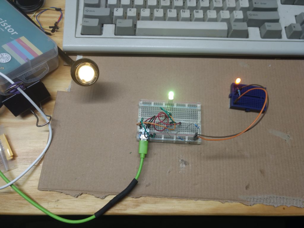
I will be the first to admit this is a terrible picture.
Above is the MkI on the left, the MkII configuration described above in the middle, and on the right was a regular yellow LED I had on hand. As you can see the light in the middle is a lime green. After some trial and error I found the a nice amber color using a 100Ω resistor for the green pin and a 47Ω resistor for the red pin. Go figure.
So now we know how to replace the entire functionality of the Arduino in the MkI with two resistors for the MkII.
I could probably reuse the MkI enclosure but one of the pegs holding the microUSB breakout board broke off, which means I can’t plug and unplug the whole thing as I originally desired. So I will probably just redesign the whole box. Onward!
For a while I attempted to use them as network monitoring servers, but the older versions of the board were not very stable and if they had a power hiccup it would destroy the SD card it was running off.
However with the version 3 boards, I have not had any issues. I have been using one running “PiHole” as a DNS server for my household, and another one running OctoPi, which is running my 3D printer. Both have been rock solid.
There is an issue however with the initial configuration. In both the above examples, there is no mouse/keyboard/display, they are “headless”. And for (perfectly legitimate) reasons, by default SSH is not running Rasbian (the most popular Raspberry Pi OS based on Debian). Since I didn’t want to go through the effort of setting up a mouse/keyboard/display just to get SSH running, I found another way. From the official documentation:
For headless setup, SSH can be enabled by placing a file named ssh, without any extension, onto the boot partition of the SD card from another computer. When the Pi boots, it looks for the ssh file. If it is found, SSH is enabled and the file is deleted. The content of the file does not matter; it could contain text, or nothing at all.
If you have loaded Raspbian onto a blank SD card, you will have two partitions. The first one, which is the smaller one, is the boot partition. Place the file into this one.
The tricky part afterwards is finding it on your network. You can either look in your router’s DHCP logs to see which IP address was just assigned, or you could port scan your entire network for devices listening on port 22. (Maybe you will find something you weren’t expecting!) The default username is “pi” and the default password is “raspberry”.
Two hints regarding Raspberry Pi’s:
If they are going to be running “headless” just use an ethernet cable and plug it directly into your router. Just one less thing running over your wireless network. And give it a static IP address!
Put it on a UPS. Although I don’t have any evidence to back this up, my experience has been that SD cards do not handle cold reboots very well.
Wooooo FRIDAY NIGHT.
UPDATE: To add the “ssh” file to SD card via Windows 7:
Open command prompt
Navigate to root of “boot” partition of SD card
Run command “copy NUL ssh“. This creates an empty file called “ssh”.
(Before we get started, a QUICK NOTE: A founding tenet of this blog is to put out content quickly, not put out monster posts sporadically. As such, I will not be adding things like sources, citations, formatting and well-lit pictures.)
I can have some pretty paranoid tendencies. Among them is a distrust for publicly accessible phone charging stations, like the kind you see in airports, or even on the airplanes themselves, which provide a USB port to any lonely traveler. (There have been cases of malicious hardware being added to these charging stations so that the charger will attempt to remove data from the device, in addition to charging the phone.)
So far I have not needed to use these charging stations (although sometimes it would have been nice,) but recently when I tried to charge my phone in my car via the USB, the car tries to pair with the phone and do things other than charging it. So I decided to make a “power-only USB cable” (You can also buy one). This is just a cable that has does not have the wires used for transmitting data connected between the two ends. For this purpose I bought two cheap MicroUSB cables from Microcenter for like $4 each.
(ANOTHER NOTE: For the purposes of this post, I am referring to an Android smartphone. This should work on anything that is powered via MicroUSB cable, which would include things like Arduinos and (I guess older/cheaper) Android smartphones. DO NOT CUT UP YOUR IPHONE CABLE.)
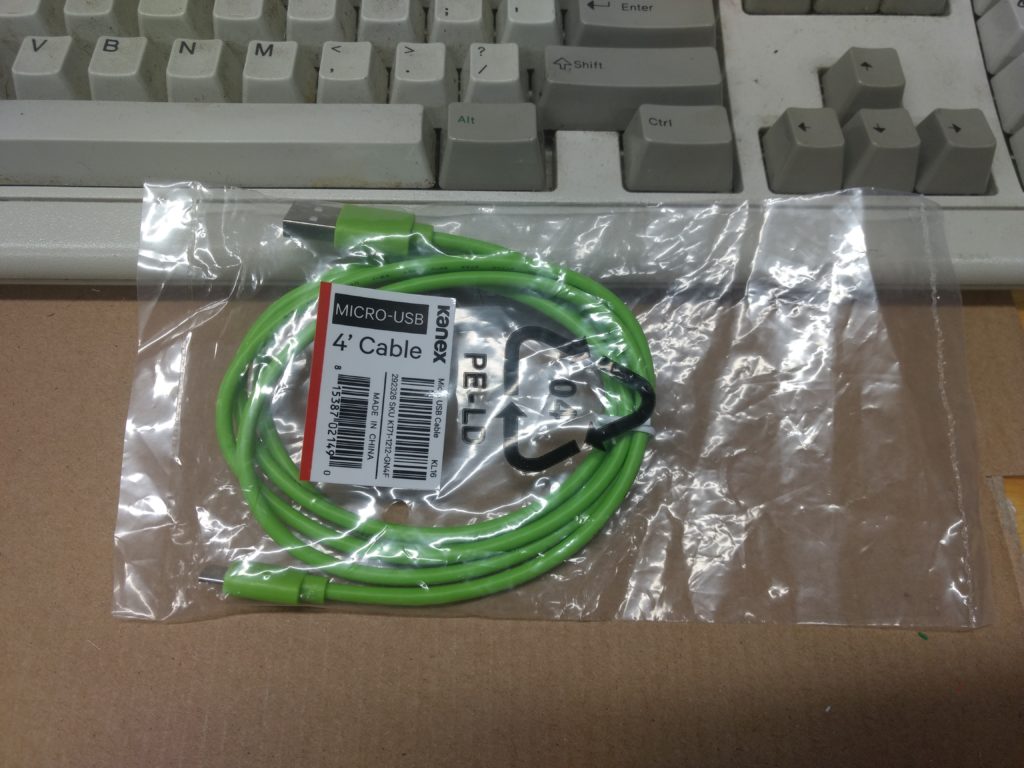
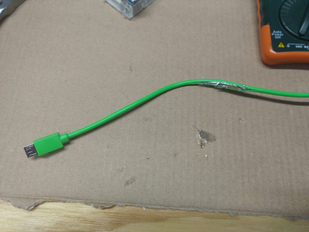
BAM FIRST PICTURE. Isn’t she a beaut?
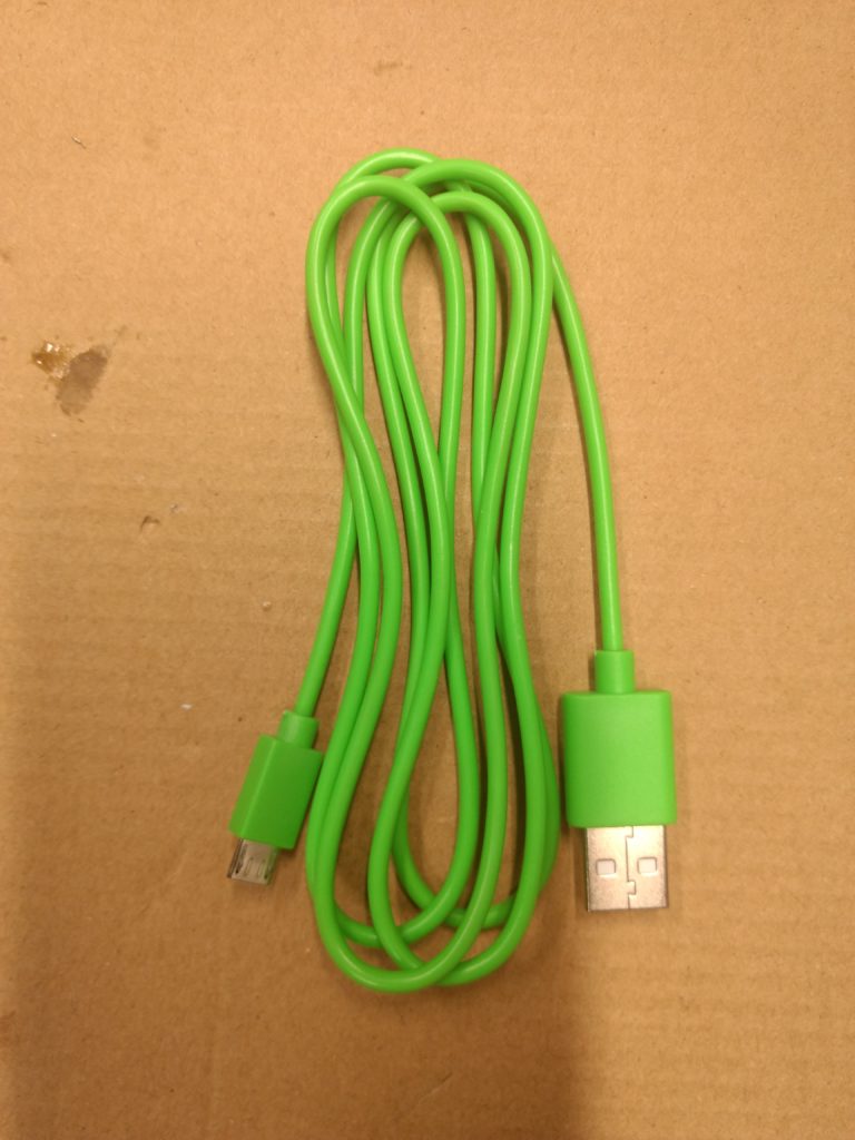
Behold! A MicroUSB cable!
Start by cutting the cable open like that time you dissected a giant worm in biology class:
Using an Exacto-esque knife.
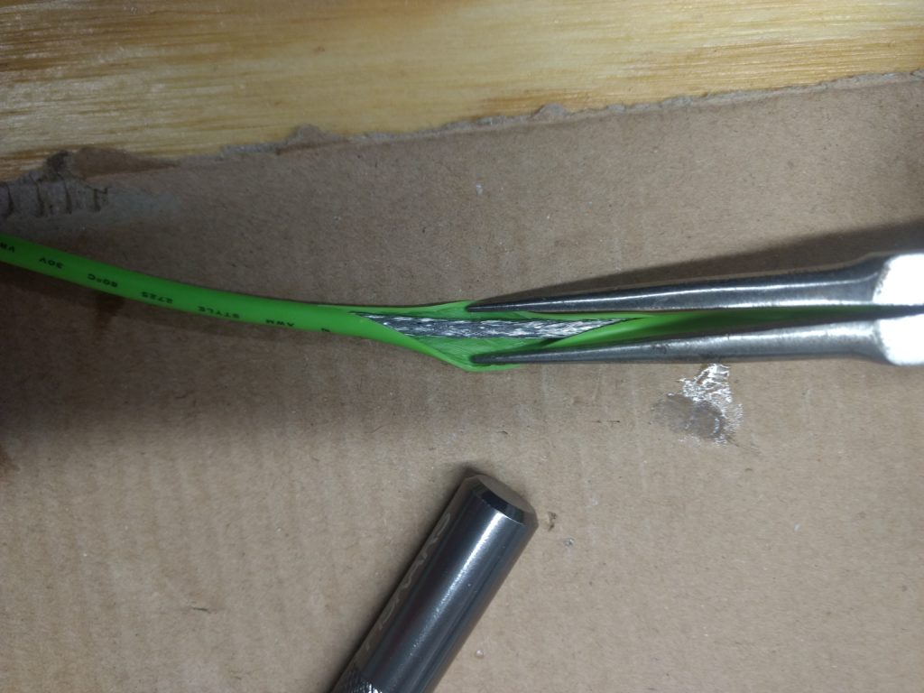
Cut through the shielding to expose the wires inside:
Please pardon the cardboard and schmutz.
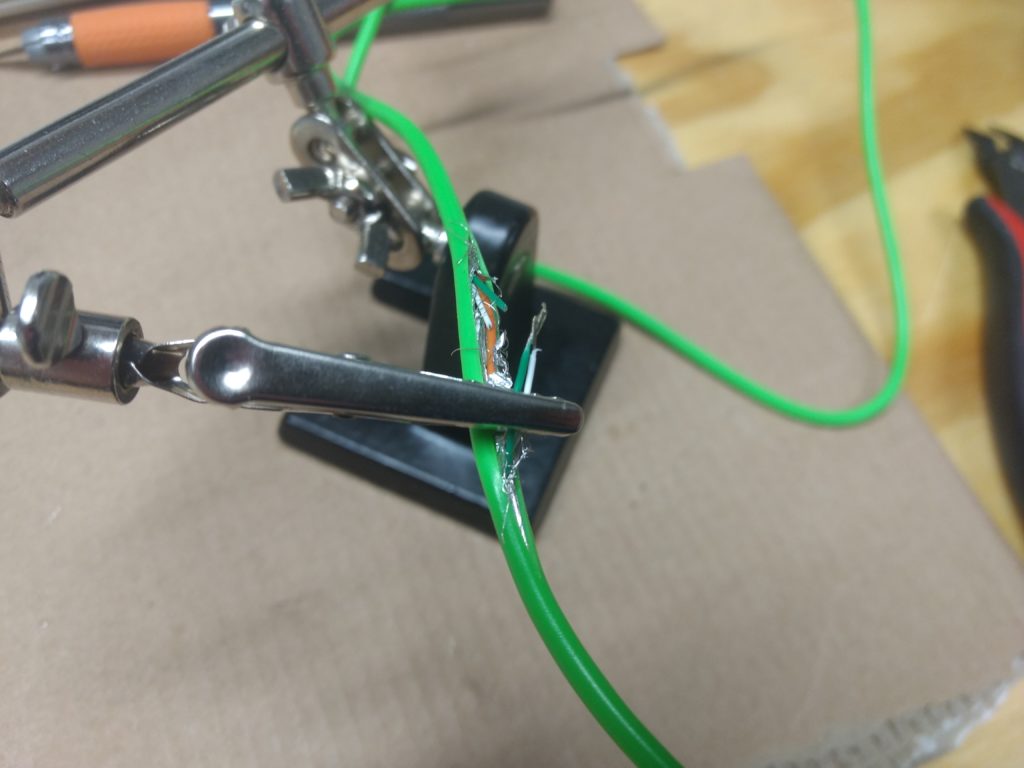
This is the important part:
A USB cable has four wires inside, two for power (usually a RED one and the BLACK one), and two for data (the GREEN and the WHITE). This one had an orange one for some reason. You are going to CUT THE GREEN AND WHITE WIRES.
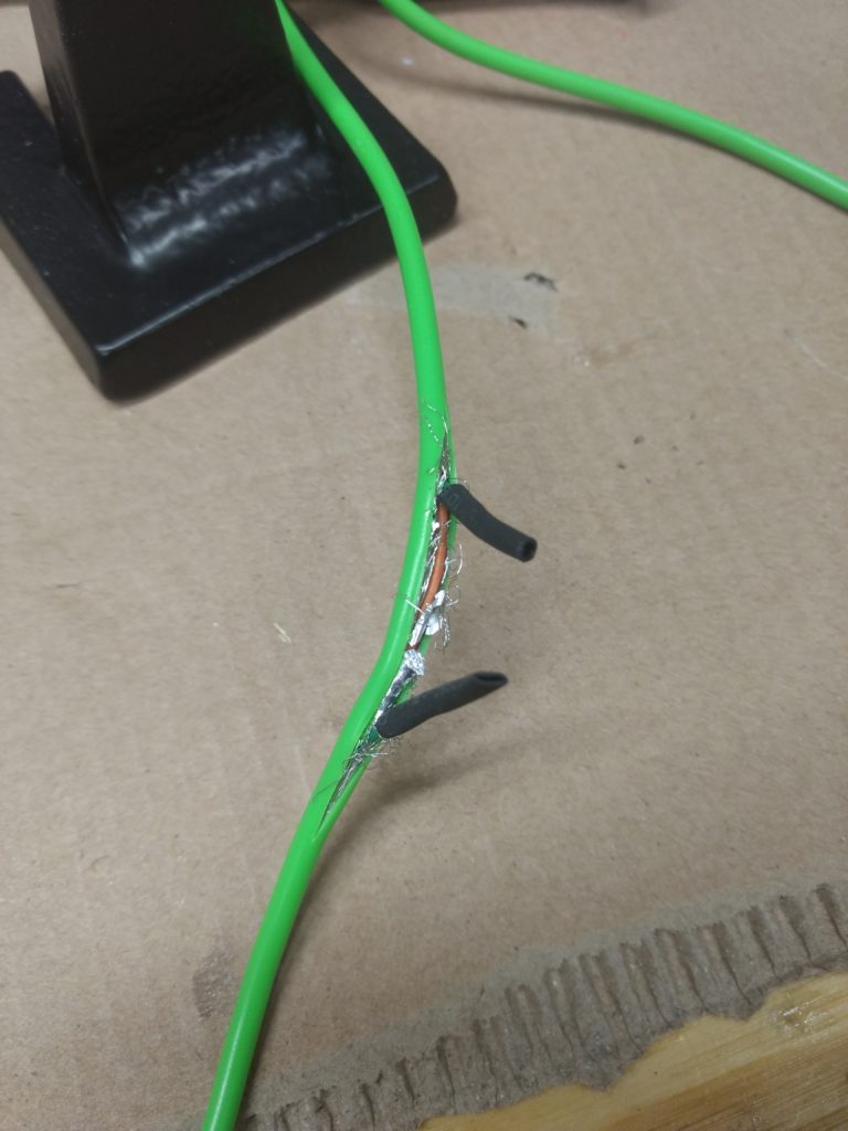
Then if you have the tools, you are going to solder them together on the MicroUSB side of the cable. (However, your device might not require this. I was able to change my phone off my computer before I soldered the wires together.) Once they are soldered together, put some heat-shrink on both sides to prevent shorts. To be extra safe I trimmed one of the wires on the non-soldered side so the ends were not close together.
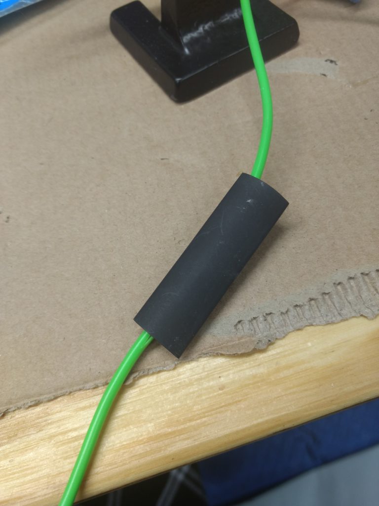
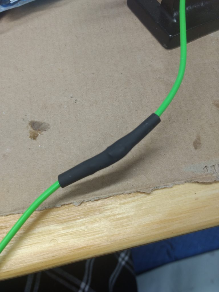
Then add some more heat-shrink over top of the whole thing:
Before
After
That’s it! And it makes a great conversation starter for your next flight! YOU’RE WELCOME.
If you have the time I recommend you just read that.
LEDs can be powered with a power source, assuming you supply the correct voltage. I have in mind a project that would be run off USB (5V), and most LEDs run off something less than that. So we need to add a resistor to bring the 5V’s down to something the LED can run without burning out. This requires some light (ha!) math that is better explained in the Adafruit post.
LEDs have a short leg and a long leg. The SHORT one is NEGATIVE (GROUND/BLACK). The LONG one is POSITIVE (THIS IS THE RED WIRE).
The resistor goes in between the SHORT LEG and GROUND.
Your LED also has something called a FORWARD VOLTAGE, which for mine is listed on the supplied datasheet as “2.8~3.2V” so we’ll call it 3V.
This is probably my fifth attempt at operating a blog, and it’s been a while since my last attempt. Are we still calling them blogs?
During my previous attempt I spent a quarter of the time actually writing content, a quarter of the time making the content fun and witty, and the rest of the time managing the Linux/Apache/PHP stuff. But privacy is very importance to me, so I didn’t want to go with a social media site. So I chose a hosted WordPress solution.
The purpose of this going to be documenting my various projects and other helpful things I come across and feel like sharing. At the moment I have no interest in monetizing any of this, but I am a big fan of cryptocurrencies so I might integrate BAT at some point.
My other big hobby at the moment is 3D printing. I have been running a Monoprice Select Mini for about a year now and I am still using it to make stuff, so that’s probably what most of this will be about.